Many virtualization administrators get confused with Hyper-V network virtual switch’s capabilities. A network virtual switch in Hyper-V operates at Layer 2. Apart from operating at Layer 2, it maintains a MAC table that contains the MAC addresses of all the virtual machines connected to it. 
A Virtual Switch created on Hyper-V can have unlimited Virtual Machines connected to it, and the virtual switch operates in one of two modes: Trunk Mode or Access Mode. There are three types of virtual switches that can be created in Hyper-V: External, Private and Internal Virtual Network Switch.
External Virtual Network Switch allows communication between virtual machines running on the same Hyper-V Server, Hyper-V Parent Partition and Virtual Machines running on the remote Hyper-V Server. It requires a physical network adapter on the Hyper-V Host that is not mapped to any other External Virtual Network Switch. As a result, you can create External virtual switches as long as you have physical network adapters that are not mapped to any other external virtual switches.
Internal Virtual Network Switch can be used to allow communication between virtual machines connected to the same switch and also allow communication to the Hyper-V Parent Partition. You can create any number of internal virtual switches.
Private Virtual Network Switch allows communication between virtual machines connected to the same virtual switch. Virtual Machines connected to this type of virtual switch cannot communicate with Hyper-V Parent Partition. You can create any number of Private virtual switches.
As stated earlier, Hyper-V Virtual Network Switches can be configured to work in either Access Mode or Trunk Mode, as is the case with a physical switch. These two modes are co-related with the VLAN ID Tagging system.
Only External and Internal Virtual Switches can be configured in Trunk Mode and Access Mode. You can assign a VLAN ID to these switches but an option for assigning a VLAN ID to a Private Network Virtual Switch is not available.
In Trunk Mode, a virtual switch will listen to all the network traffic and forward the traffic to all the ports. In other words, network packets are sent to all the virtual machines connected to it. By default, a virtual switch in Hyper-V is configured in Trunk Mode, which means the virtual switch receives all network packets and forwards them to all the virtual machines connected to it. There is not much configuration needed to configure the virtual switch in Trunk Mode.
In Access Mode, the virtual switch receives network packets in which it first checks the VLAN ID tagged in the network packet. If the VLAN ID tagged in the network packet matches the one configured on the virtual switch, then the network packet is accepted by the virtual switch. Any incoming network packet that is not tagged with the same VLAN ID will be discarded by the virtual switch.
Configuring a Virtual Switch in Access Mode
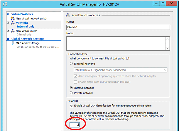
To configure a virtual switch in Access Mode, first open the Virtual Switch Manager. Next, select the virtual switch you want to configure and click the “Enable VLAN identification for management operating system” check box, as shown in the below screenshot.

Finally, specify the VLAN ID in the text box as shown in the red circle in the below screenshot. This configuration will force the virtual switch to receive network packets which are tagged with the VLAN ID which is configured on the virtual switch.
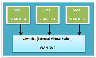
To better illustrate this with an example, let’s say there are three virtual machines running on a Hyper-V Server: VM1, VM2 and VM3. VM1 and VM2 are configured with a VLAN ID 4, and VM3 is configured with a VLAN ID 5.
These virtual machines are connected to an External Virtual Switch called “vSwitch1” that, in turn, is configured with a VLAN ID 4 (configured in the Access Mode) as shown in the below image.

As you can see above, Virtual Switch (vSwitch1), which is an External Virtual Network Switch, is configured in Access Mode. Since it is configured in Access Mode, it can only receive network packets that are tagged with the VLAN ID 4.

